 The component choice an electrical engineer starts with the functional requirements of the circuit. Another consideration is the rated values of the specific component selected.
Derating guidelines provide information to compare the component rated values to select stresses or conditions. The intent is to assist the engineering team to select robust enough components for the application.
Robust here implying the component within the circuit will operate for a suitable length of time.
Vendor derating guidelines
The maximum rated values for a component do not imply the component will last a suitable length of time when operated at or near the maximum rated values. The component will operate for some duration, often a relatively short duration, before failing.
The component will operate for some duration, often a relatively short duration, before failing.
Let’s look at a specific situation. Let’s say we are designing a circuit and would like to use a Kemet T521 High Voltage polymer electrolytic (a solid tantalum device). The application has a nominal steady-state applied voltage of 24 Vdc.
The design team expects the operating ambient temperature near the capacitor to be 50°C.
Kemet provides a 25 Vdc and 35Vdc rated components. Both have the option for a maximum temperature rating of 105°C and 125°C. There are cost and size differences, so which component should you select?
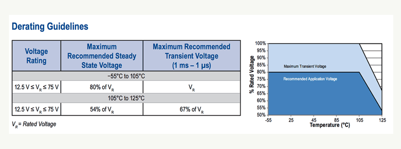
Kemet does provide derating guidelines within the data sheet for the T521 family of parts.
 From http://www.kemet.com/Lists/ProductCatalog/Attachments/252/KEM_T2016_T521.pdf KEMET Organic Capacitor (KO-CAP (R) —Industrial, T521 High Voltage Polymer Electrolytic, 12.5 – 75 VDC, accessed 20 July 2016.
This implies we should not select the 25 Vdc rated device as it would provide only 96% derating. The 35 Vdc rated device would provide 69% derating. Given the operating temperature of 50°C the 35 Vdc rated device is less than the recommended 80% of Vr.
For the operating temperature, Kemet includes in the graphic of %Rated Voltage versus Temperature additional voltage derating guidance when the operating temperature is above 105°C.
Since our application is at 50°C, it is not a concern.
Industry derating guideline
There are derating guidelines for different industries generally focused on different types of applications. NASA, NavAir, and others have publicly available derating tables.
Let’s look at the NavAir guideline as I have it available and it is comprehensive.
For a Fixed, Tantalum, Chip component, the guideline recommends using a capacitor with 60% of rated maximum voltage. In this case, the 35 Vdc device would be suitable for a circuit applied voltage of 21 Vdc, which is below our expected operating voltage.
The 50 Vdc rated device would meet the derating guideline, yet is larger and more costly.
The NavAir guideline recommends the operating temperature should be 10°C below the maximum rated temperature.
Either the 105°C or 125°C rated components would work for our application.
Impact of going 0ver or under the guidelines
Vendor and industry guidelines provide a means to select components suitable for our application.
Yet, the guidelines do not provide information concerning the impact that selection will have on failure rates or expected time to failure values.
In general, if we apply less stress on the component the longer it will function. Using a component above the rated values is called uprating, and should be done with care.
The Kemet data sheet does include Performance Characteristics including the results of an endurance test. The data sheet lists endurance at 105°C and at rated voltage the capacitor will survive 2,000 hours. At 125°C at 2/3 the rated voltage, it will again survive 2,000 hours.
2,000 hours is about 3 month if operating full time. It is not very long. Luckily we are not going to use the capacitor at rated voltage or temperature. Derating the voltage and operating at a lower temperature should increase the expected endurance.
The data sheet and the derating guidelines are mute on how endurance will improve though.
Selecting a component that will meet derating guidelines may or may not meet our endurance requirements.
We need better information to determine the impact of expected life or endurance.
Voltage relationship to time to failure
Using a capacitor at less than rated voltage does provide a reduction of voltage stress within the capacitor. This reduces the dielectric damage and lengthens the time to failure.
Kemet engineers, Erik Reed, and George Haddox published a paper that studies the relationship between applied voltage and time to failure in 2011.
Specifically, for the capacitor type, we are considering they found the time to failure is a function of rated voltage over applied voltage

Where t1 is the time to failure (characteristic life) for the capacitor in its application
t2 is the expected time to failure for the capacitor when used at rated voltage
V1 is the application or applied voltage
V2 is the maximum rated voltage
Eta is a determined from the accelerated life testing data and described the relationship between voltage derating and time to failure.
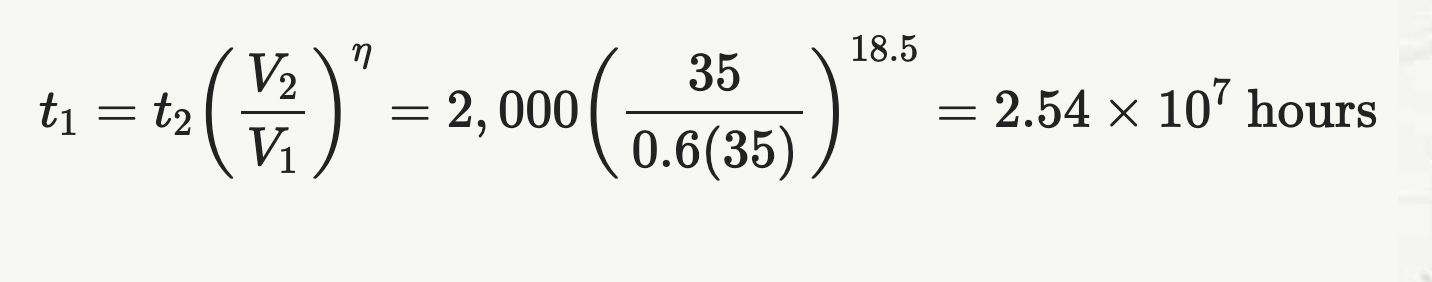
If we derate voltage by 60% and given the expected endurance is 2,000 hours at maximum rated voltage of 35 Vdc, plus the eta value of 18.5 (from the Reed and Haddox paper) we can calculate the expected life of the capacitor as
Instead of operating a 35 Vdc rated device at 21 Vdc we expect the voltage to be 24 Vdc. Using the same equation we can estimate the life the operating slightly above the recommended (NavAir) 60% derating as
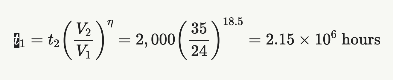
About an order of magnitude less expected life when operating just 3 volts above the recommendation.
Another way to plot derating information
The calculations above for just two voltage values led me to think about visualizing the relationship between the applied voltage, maximum rated voltage and expected lifetime.
Using the NavAir recommended 60% derating as the baseline, we can normalize the change in a lifetime by dividing the calculated t1 for the actual voltage divided by the calculated t1 for the nominal derating expected life.
This means the time to failure multiplier is one when we select a component with a derated value that matches the applied voltage.
When the applied voltage is above the recommended derated voltage (24 Vdc instead of 21 Vdc in above example) we can calculate the adverse impact on reliability.
If the applied voltage is below the recommended derated voltage we can determine the benefit to reliability.
The following plot shows the time to failure multiplier for a range of operating voltage over maximum rated voltages.
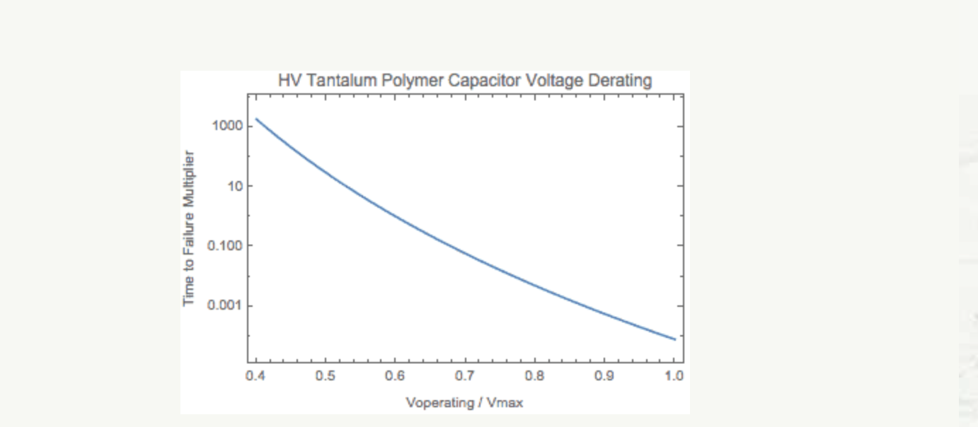
At 0.6 (60%) operating voltage over maximum rated voltage the time to failure multiplier is equal to one. A higher derating value, the multiplier is less than one and indicated a corresponding reduction in expected endurance.
At an 80% derating (Kemet recommendation) the calculated time to failure is 1.24 x 10^5, which is a little over two orders of magnitude below the 60% derating value.
Here is the impact of operating temperature on the time to failure multiplier

According to the Kemet, the derated temperature is 105°C. Operating at 50°C provides a 1,280x multiplier or improvement to the expected time to failure duration. The based expected endurance at 105°C is 2,000 hours.
The graph for temperature is based on the time to failure model created in the paper by Reed and Haddox. They used an Arrhenius equation with an activation energy of 1.37 eV/K.
Conclusion
So, what do you think of the plots?
Does it help to visualize and quickly estimate the impact of specific stress values impact on expected reliability? Does it make sense?
What do you think? What are your questions?
Bio:
Fred Schenkelberg is an experienced reliability engineering and management consultant with his firm FMS Reliability. His passion is working with teams to create cost-effective reliability programs that solve problems, create durable and reliable products, increase customer satisfaction, and reduce warranty costs. If you enjoyed this articles consider subscribing to the ongoing series at Accendo Reliability